Filco Majestouch 2 Cable Repair
12 Years of Faithful Service
My Filco Majestouch 2 Keyboard (with Cherry MX Brown switches) has served me well as a work keyboard for over a decade (I purchased on 30/01/2013).
However today when I plugged it in to my laptop it would not recognize the keyboard. I found that moving the cable around would make it connect and disconnect.
I had a look at websites for replacement cable assemblies but there was only one online store in the UK that had non braided versions. I also tried to see if there was any easy way to convert to a USB C port but I couldn’t find any quick/easy ways to do this.
Repair
This left me with one option was to try and repair the cable myself. When I initially tried to find where the break was I thought it was about 3 inches (75mm) away from the keyboard itself. However, further investigation revealed it was far closer to the strain relief.
This meant that I couldn’t patch it on the cable itself and I would need to do something a little more involved.
The screenshot below shows roughly where the problem in the cable is. It was difficult to track down as moving the cable in small ways would make the LED lights turn off and on again.
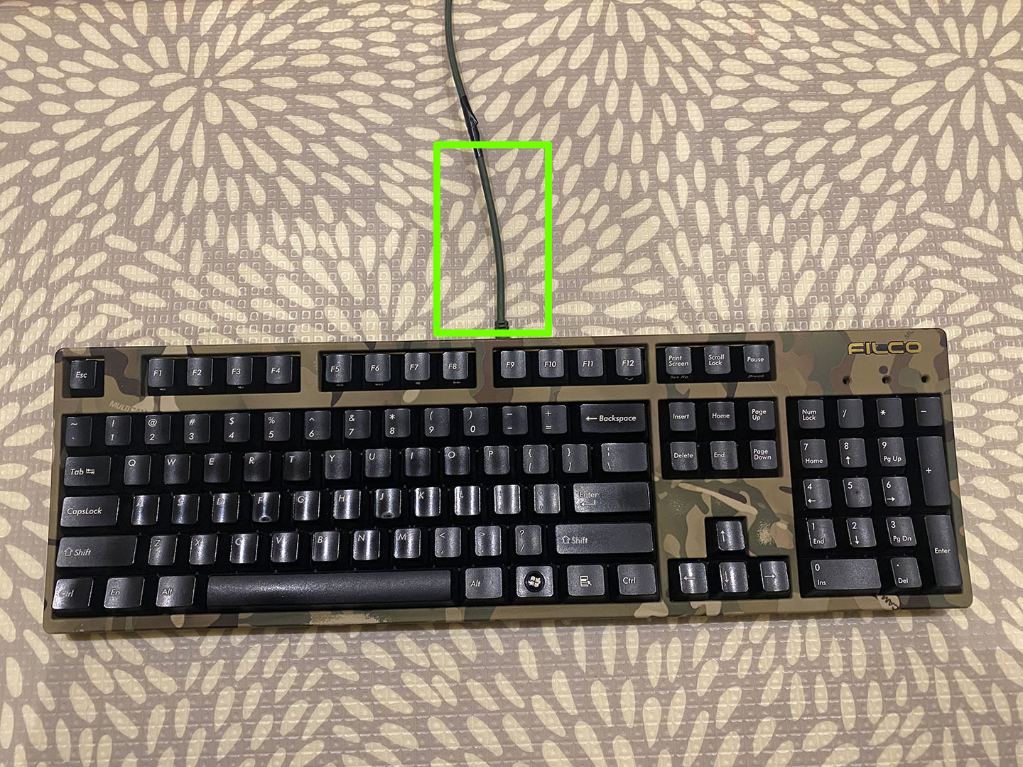
Locating cable issue
Based on the location of the issue I would have to cut out the “strain relief” on the cable but then re-attach the PCB connector in some way.
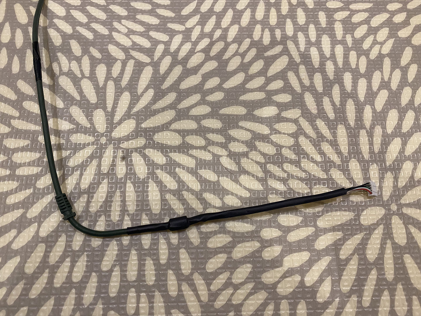
Original internal cable
As you can see from the original cable there is the strain relief and what appears to be a ferrite before the wires go into the 5 pin connector. The whole internal assembly is wrapped in heatshrink.
It’s worth noting that I said a 5 pin connector. The Majestouch 2 keyboard is a USB A keyboard which has a positive and negative power wires as well as two data communications wires. The 5th wire is a ground for the cable that we will see in the near future.
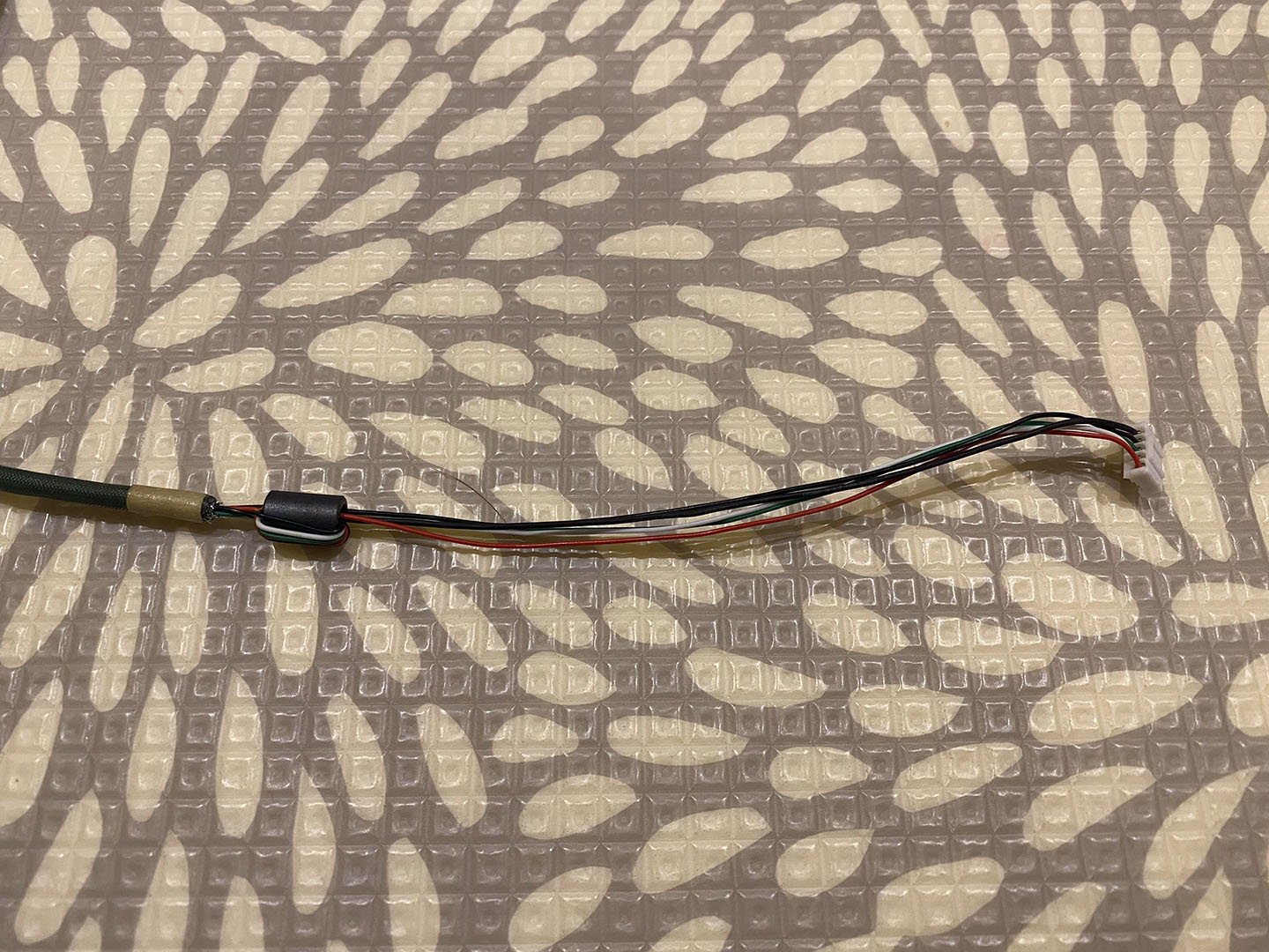
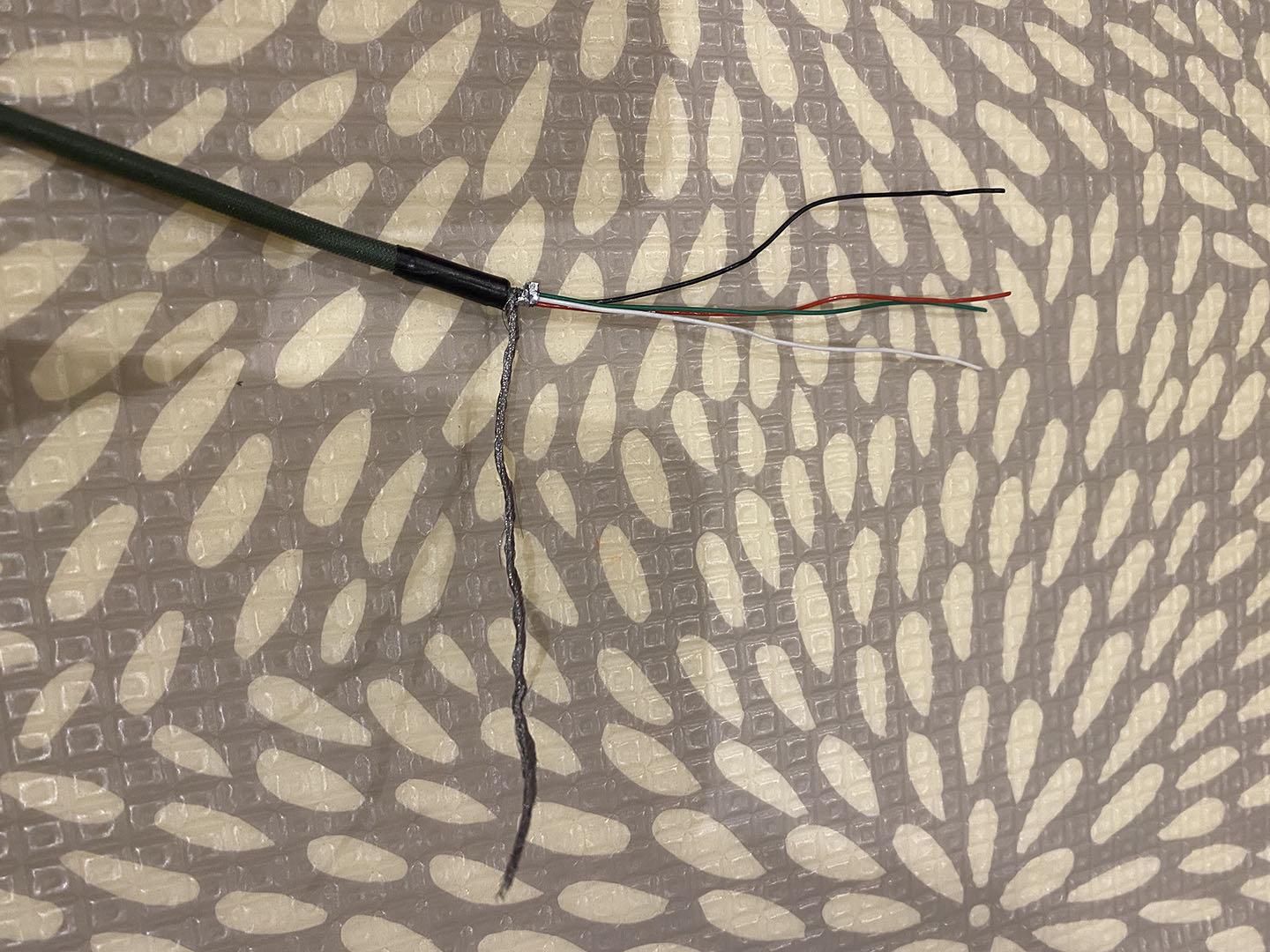
Heatshrink removed
Above you can see what the cable looks like (and the ferrite). All we need to do is to “splice out” the bad bit. This sounds easy but there is a complication with the shield (the 5th wire).
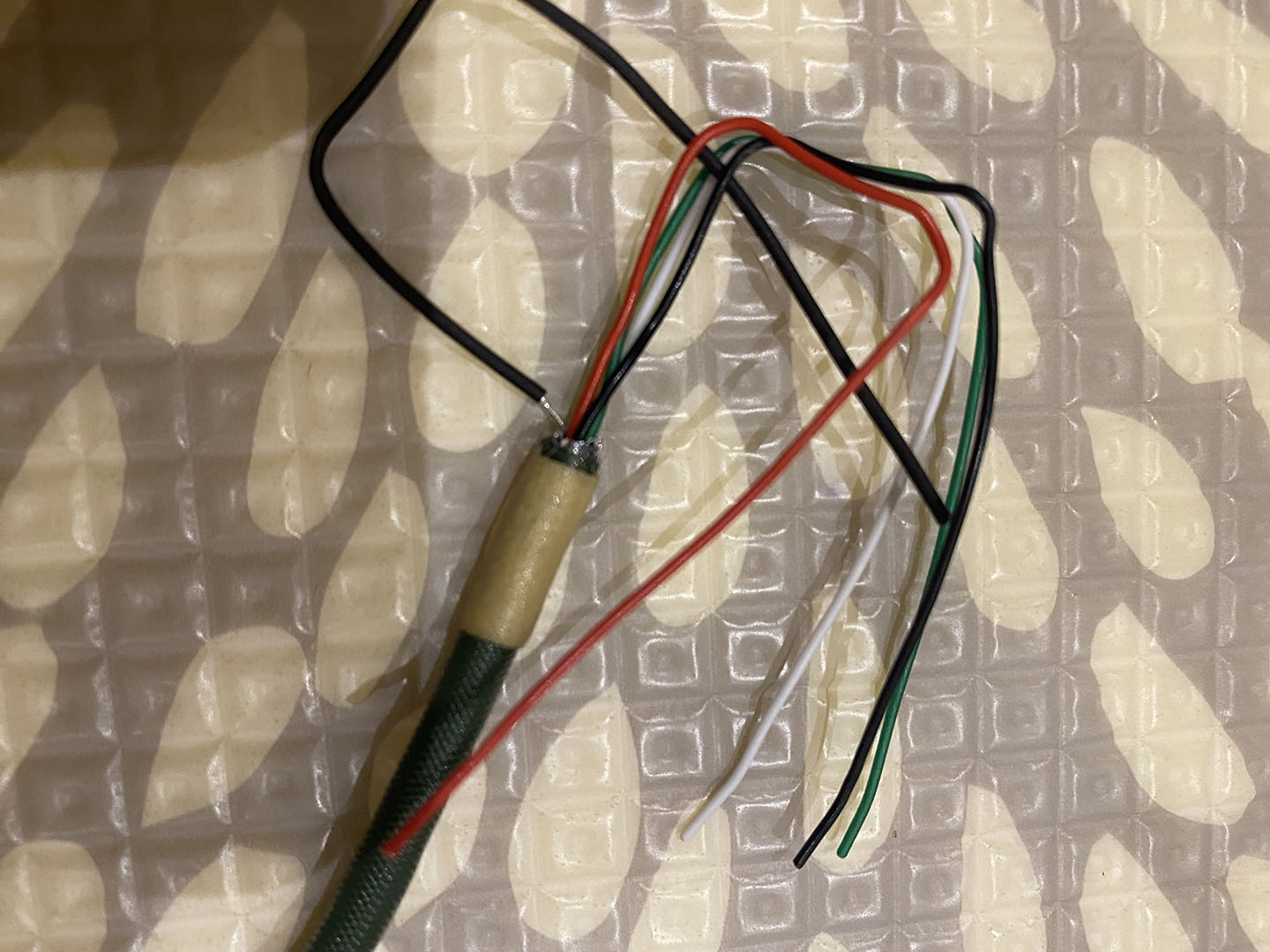
Shield wire (left one)
If you look closely at the above image the wire on the left side looks like it has a bit of the insulation missing. This is because it is not a normal wire but the shield in the cable twisted into a wire and covered in heatshrink.
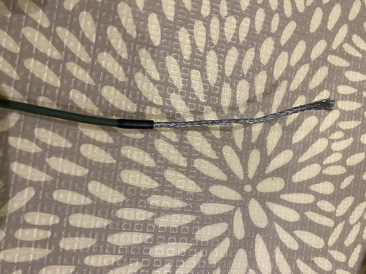
Cable shield
The shield in a cable is designed to reduce interference from external signals. In the above image you can see that in this cable it takes the form of a mesh.
Some cables have a single “naked” wire running though the cable and then all the cables are wrapped in a foil.
Twisted shield
To create a wire from the shield is not difficult but is a bit tedious for mesh shields like this. You basically have to “un-braid” it like hair little bits at a time.
This can then be covered in heatshrink for safety.
I had to do this twice as the first time (in the picture above) I included all the shield which was quite thick. This wouldn’t fit in the ferrite (see image below) so I had to remove the heatshrink and reduce (cut out) some of the shield wires to reduce the overall diameter of the completed wire.
Importantly I needed to slide two pieces of heatshrink onto the cable before we attache the ferrite to the cable.
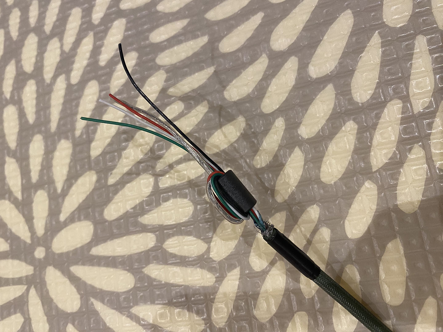
Ferrite installed
As you can see above all the wires and the shield wire need to tightly go through the ferrite, loop back over and through again. As stated above I needed to modify the shield wire as it was just too thick to pass through with the other wires.
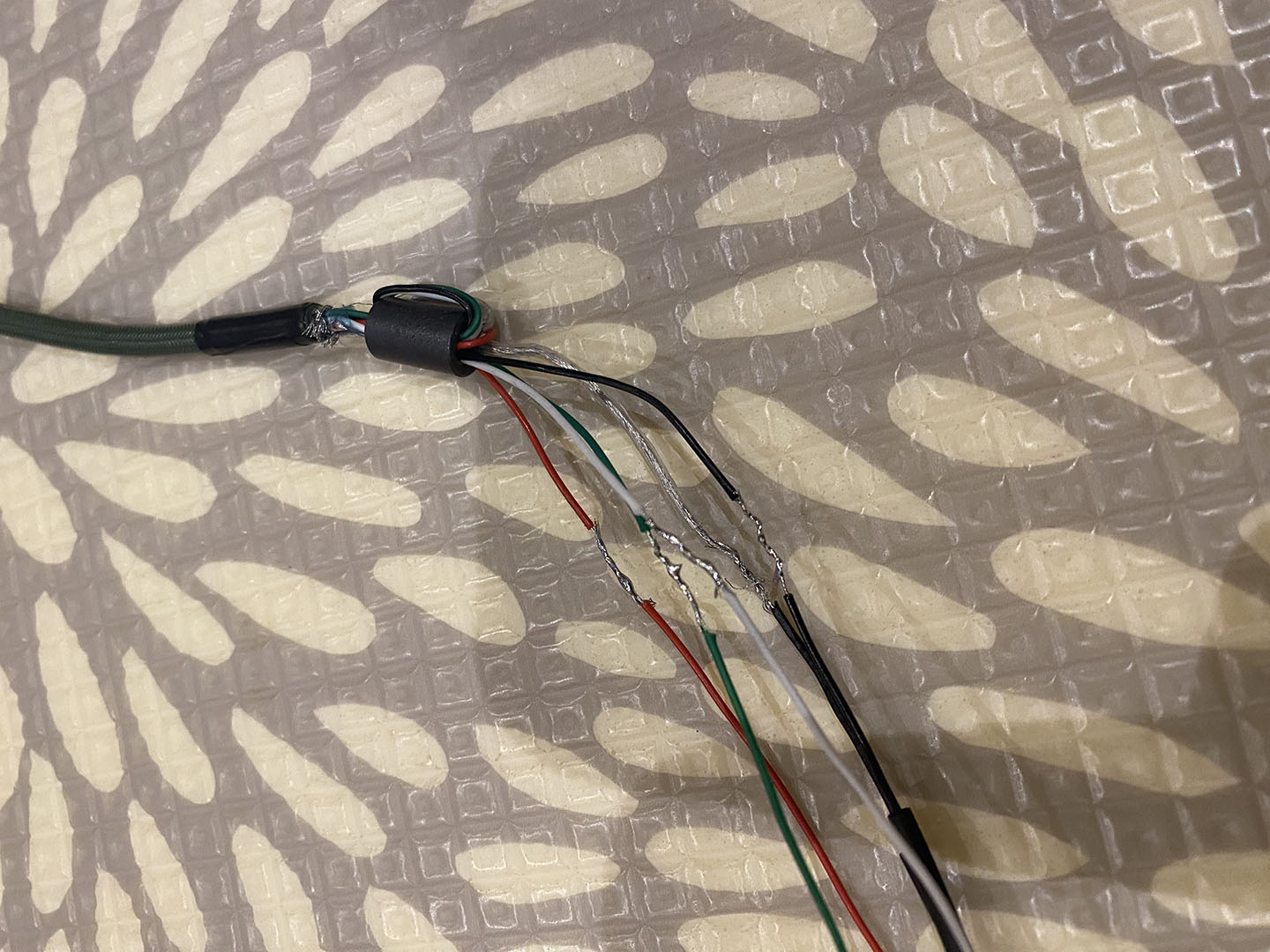
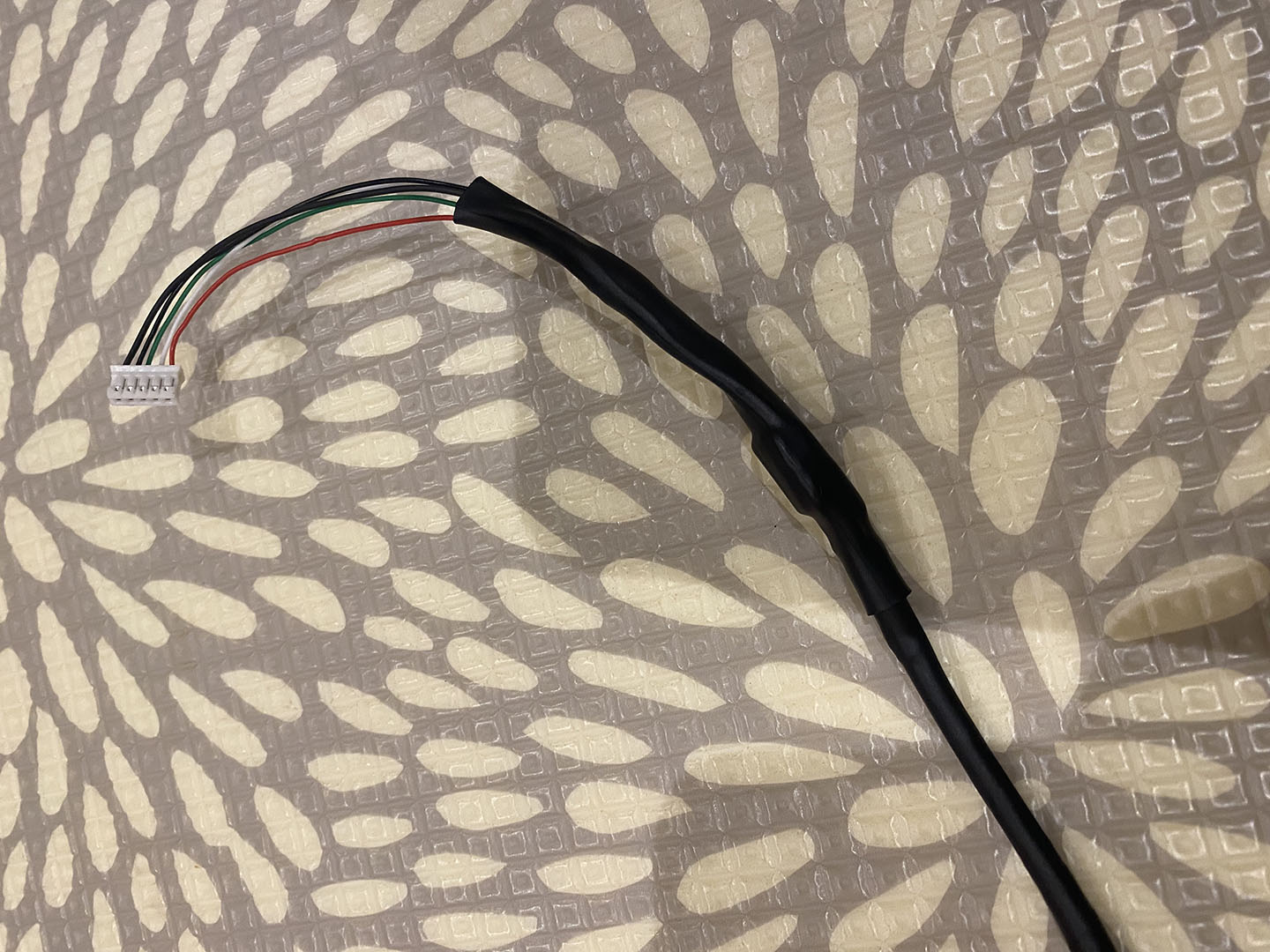
Soldered cables
I then had to strip the wires on both sides ready to solder the wires together. However, the red wire (as you will see in the later pictures) broke when I stripped the insulation off making it just less than 10mm shorter. The main wires are very fragile so I didn’t want to risk cutting the others shorter to match as there is not a lot of cable to work with in this space.
I had to slide more heatshrink on each wire to insulate them from one another.
The cables could then be soldered together and the joins covered with heatshrink.
After this the remaining heatshrink could be slid onto the wire and over the ferrite being shrunk accordingly.
Completed cable repair
Above you can see the completed cable repair. Although it does not quite look as good as factory I’m pretty pleased with how it turned out.
It did fit all in the case alright (luckily the slightly shorter red cable wasn’t an issue) and mostly was held in place by the same cable “grabbers” inside the case.
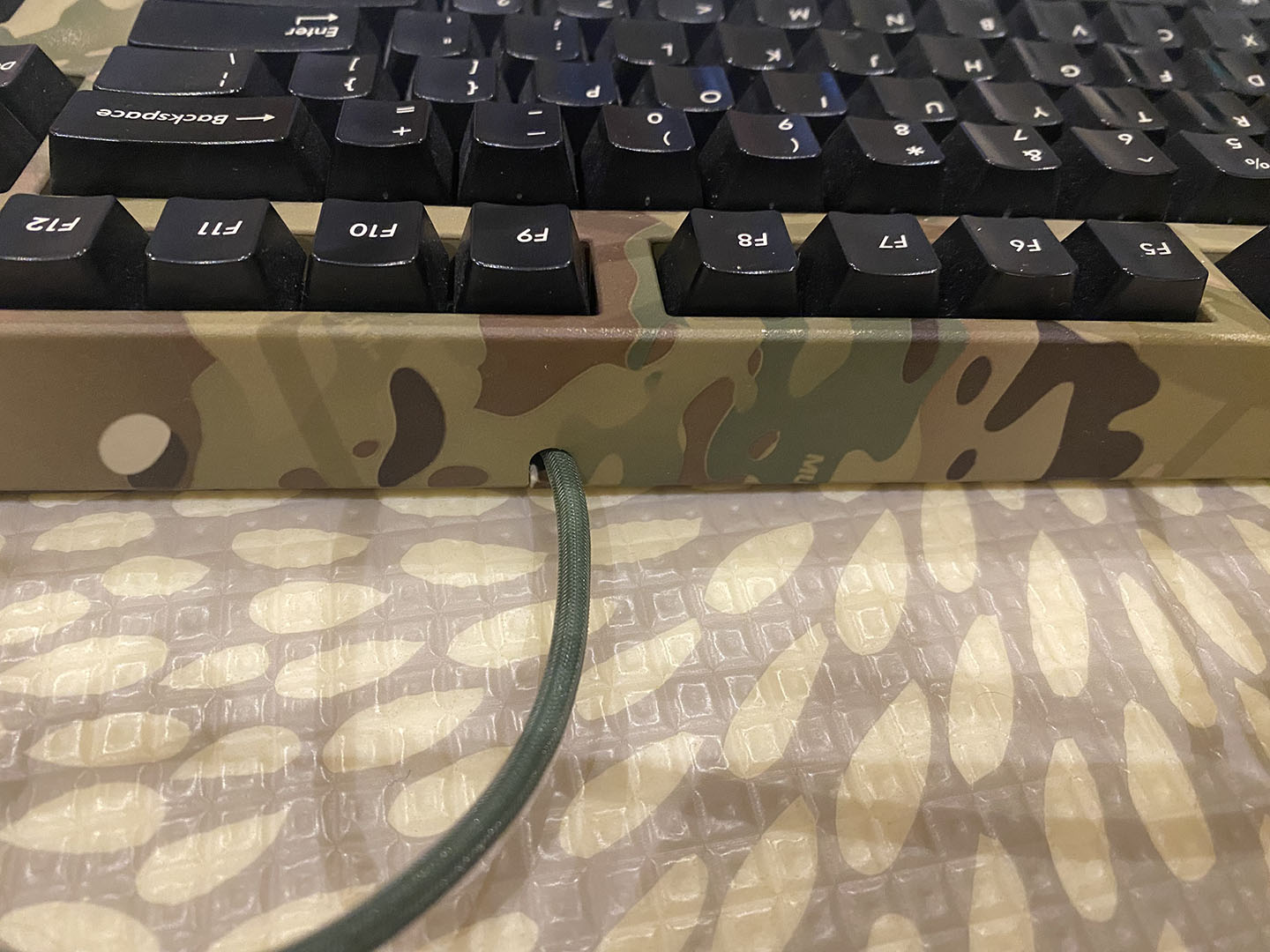
Completed outside view
I even think the view of the outside of the cable looks okay IMO. Strain relief is not going to be an issue as the cable is held pretty tightly internally.
Overall this worked pretty well and I’m glad that this keyboard is going to get some extra life.